
A DIY Stand for the PM Benchtop Milling Machine.
The amount of machinery I’ve moved in my adult life is quite staggering. In the past 12 years I’ve built up and sold off 4 different shops of various sizes and capabilities. It seems every time I get settled a new opportunity or job takes me somewhere else and with these moves it hasn’t always been cost or time effective to bring everything along. So in each new location I have to continually fight the strong desire to own every piece of large manufacturing equipment I see on CL. To make matters worse, in my most recent relocation to San Francisco real estate comes at a premium. While the space I’m renting has a fairly large garage, strictly from a square footage perspective, it’s not really conducive for large equipment. First, the garage door is really small both in width and height. Second, the garage floor is terribly uneven. There’s a massive slope down into the garage and it sort of undulates like the sand dunes it was built on over 50 years ago. So yeah, large heavy equipment didn’t really seem like something I was ready to take on here, even with the experience.
I did however, know that I wanted a mill at home. Something to fab up simple brackets, parts or prototypes for ideas I wanted to test or simply to hold. I’m a firm believer that good ideas comes from an iterative cycle of design & make, that you have to touch, hold, and use what you design to know if you are converging on a solution. For me having a mill at home would help unlock that ability in all hours of the day. And having a small mill at home would save me the trouble of trying to figure out how to get it in the garage. Now, I know the debate, in fact I’ve always been on the other side that bigger & more rigid is always better. I still believe that to be true, but I also believe that operating within your means (that includes space) is more important than not having anything or breaking the bank or other constraint to have something. I’d rather machine slower and with less cut depth than to not machine anything at all. So for this particular space, for this particular shop, I settled on a bench mill. The one I ended up picking (after extensive research) was the Precision Matthews PM-727V Mill with a DRO. I won’t get into the nitty gritty on this post, since I’m already rambling a bit and this is supposed to be a blog about a DIY stand. But the main reasons were 110V, Variable Speed & the 3” Quill Travel. Now that I had a mill selected, I needed somewhere to put it. By somewhere, I meant something and by put it, I meant put it on.
The idea and Product Requirements
When I was first looking to purchase the mill, I was honestly considering pulling the trigger on the stock stand. At $199.00 extra it’s actually a pretty good deal for what it is. However, back to living in the Bay Area (where I told you already square footage comes at a ridiculous cost) these last few years have seriously conditioned me to always think how to operate efficiently in a smaller space. After all, I don’t know how long I’ll be in this particular place. I started thinking about all that real estate under the mill. Sure, there is that swing door, and probably some shelves in there, but I have that on my lathe and to be honest, it’s kind of a pain. Don’t get me wrong it’s better than nothing, but things are still always get pushed to the back and I always find myself crouched down, cursing under my breath trying to reach in and find/grab the things I need. I much prefer a drawer system like those found on actual tool boxes, that when pulled out everything is laid out nice and neat in front of you.
In addition to my feud with “pantry-style” tool storage, there’s the other complicated fact I mentioned before. That my current garage is probably the most uneven concrete surface on the face of the planet. I’m not really sure what the home builders were thinking when they put in the garage, but it seems they built the house and had a bit of extra headroom in the crawlspace underneath it so they shoveled a hole and filled it with 10 inches of cement. It’s actually so bad in some spots that you have to pay attention when you are walking across it otherwise a sudden rise or dip will sneak up on you and you’ll catch yourself straight trippin’. Anyways, given that situation and looking at the stand/machine it looked a little top heavy and at first glance I was unsure about the leveling strategy. This was the official turning point when I decided to build my own. After all it was going to be simple right? I mean, I only had 3 main product requirements: drawers, a wider sturdier base, and the ability to level it easily. I also hadn’t welded anything in nearly 6 years. What could go wrong?
The FRAME Design & RAW MATERIAL SOURCING
When I started thinking about incorporating drawers, I converged on the easiest way of doing this to be buying a base tool chest rather than having to build my own. A number of manufacturers do a pretty good job on their drawer systems for relatively cheap and it’s something I didn’t want to spend a lot of time chasing down or designing myself.
I ended up where all good investigations start these days, scouring the internet looking for something suitable. However, to my frustration my initial efforts ended in failure as I couldn’t quite find the right one. Either the size was wrong, it didn’t have an optimal drawer configuration or the color was off (hey form over function right?) My luck began to turn around the very next week, with grace of the Tool Chest Gods smiling down upon me, I had to go on a business trip to visit a vendor for my day job. Now while I’m one to not think any business trip is a favor of good fortune, at their facility they had this awesome tool chest that we were pulling stuff from. I really loved the way the drawer latching mechanism worked and it instantly clicked that this would be the perfect solution. That particular tool chest was the Craftsman GripLatch Tool Box. When I got home I continued the search, now with the model narrowed down it was a lot easier. I was fortunate enough to find the cabinet on searsoutlet.com, and even more fortunate that one was pretty close to my house for pickup! All in all I paid ~$140.00 for it, although it does seem the price fluctuates a bit from time to time. The exact tool chest I used can be found here.
With the heart (tool chest) of the stand selected I jumped into CAD and quickly mocked up the frame in 1.5 x 0.083” Square Tubing. For my CAD system I use SolidWorks. I’ve used quite a few over the years (CATIA, Inventor, NX, Fusion) and I always keep coming back to SolidWorks. For me it makes the most sense for how I like to design and manage my parts. If I was just starting out or didn’t have access to SolidWorks, I would probably use Fusion 360. It’s super affordable (free for personal use) and also a really powerful CAD system. Anyways, back to the reason we are all here! The stand dimensions are 30.00” wide by 32.25” tall x 26.50” deep. The width and height are driven 100% by the size of the tool chest, it fits with 0.125” on each side of it. Where as the depth is driven by the PM-727V Mill size. There’s a cross brace on the bottom to support the back of the tool chest at 17.50” from the front of the frame to the back surface of that brace. Then on the top there are two braces that are positioned at the milling machine mounting positions 7.50” from the opposing faces.
Now that I had a plan, it was time to find some steel. Originally I was going to use something like Online Metals to buy the materials, but actually found a local shop here in San Francisco called Bay Metals. I can’t say enough about their prices and service (they are always happy and helpful). I saved roughly about 50% of the cost by going with them. The only downside is the shortest length they sell material in is 20ft lengths. They do however have an abrasive chop saw at the shop you can use to cut the material down to fit in the car. Public Service Announcement: I will say that chop saw comes with absolutely no ear or eye protection so make sure you bring that along if you are planning on not going deaf or taking sparking steel bits to your moist, supple eye balls.
PLOT TWIST - ADDITIONAL “THINGS” REQUIRED
To facilitate with building this thing, I needed a couple tools. Actually, now that the cats out of the bag, until this project I didn’t have a welder at my home shop. Pretty hard to make a frame without one of those… I had to sell my old Lincoln Precision TIG 185 when I moved overseas back in 2014. In my defense I am just starting to explore TIG seriously as a bicycle fabrication method again. Up to this point all my frames have been lugged or fillet brazed. So trying to keep the budget light and feed two birds with one scone I decided while a MIG would probably be better suited for this particular project I’d still by a TIG instead. Looking around online, reading countless reviews and most importantly operating within my means I settled on the AHP AlphaTig201XD which I bought on sale for $680.00USD. I could go on about the reason why I picked this out of all the other options on the market today, but I’ll save that for another blog post or video. I will say so far I’ve been absolutely thrilled with it and it’s a fantastic machine for what it is. In addition to the welder I also wanted to get a cheap welding table to clamp the steel to for initial tacking. I ended up with the Klutch Welding Table from Northern tool for around $170.00. It comes with a few basic clamps and standoffs that proved to be really helpful as well. Lastly to help with keeping the corners square I bought the KAKA AC-60 angle clamp. Fabrication, here we come!
Welding the Frame
Now that I was equipped to take this project on, I started building. You can see the progress pictures in the gallery below. For all my cuts I used my Makita Cold Cut Chop Saw, it’s well worth its weight in gold. I started out by building the top and bottom frames first as sub-assemblies. I did 45 degree joints for these so I didn’t have to worry about sealing or capping the ends of the tubes. After these were finished, I ground the inside faces and tacked on the uprights to connect the top and bottom together. This is when I did the first fit check for the tool box. It fit like a glove, but was a little difficult to slide it into position. So I added, two skids in 1/2” x 3” steel bar. You can see these in pictures 10 & 14 below. This allowed me to slide the cabinet in from the back of the stand on top of those skids. There’s also a lip on the bottom back of the tool chest that acts as a hardtop for the cabinet in the stand. By pushing it all the way into the stand from the back until this hardtop, the front of the cabinet aligns with the front of the stand perfectly.


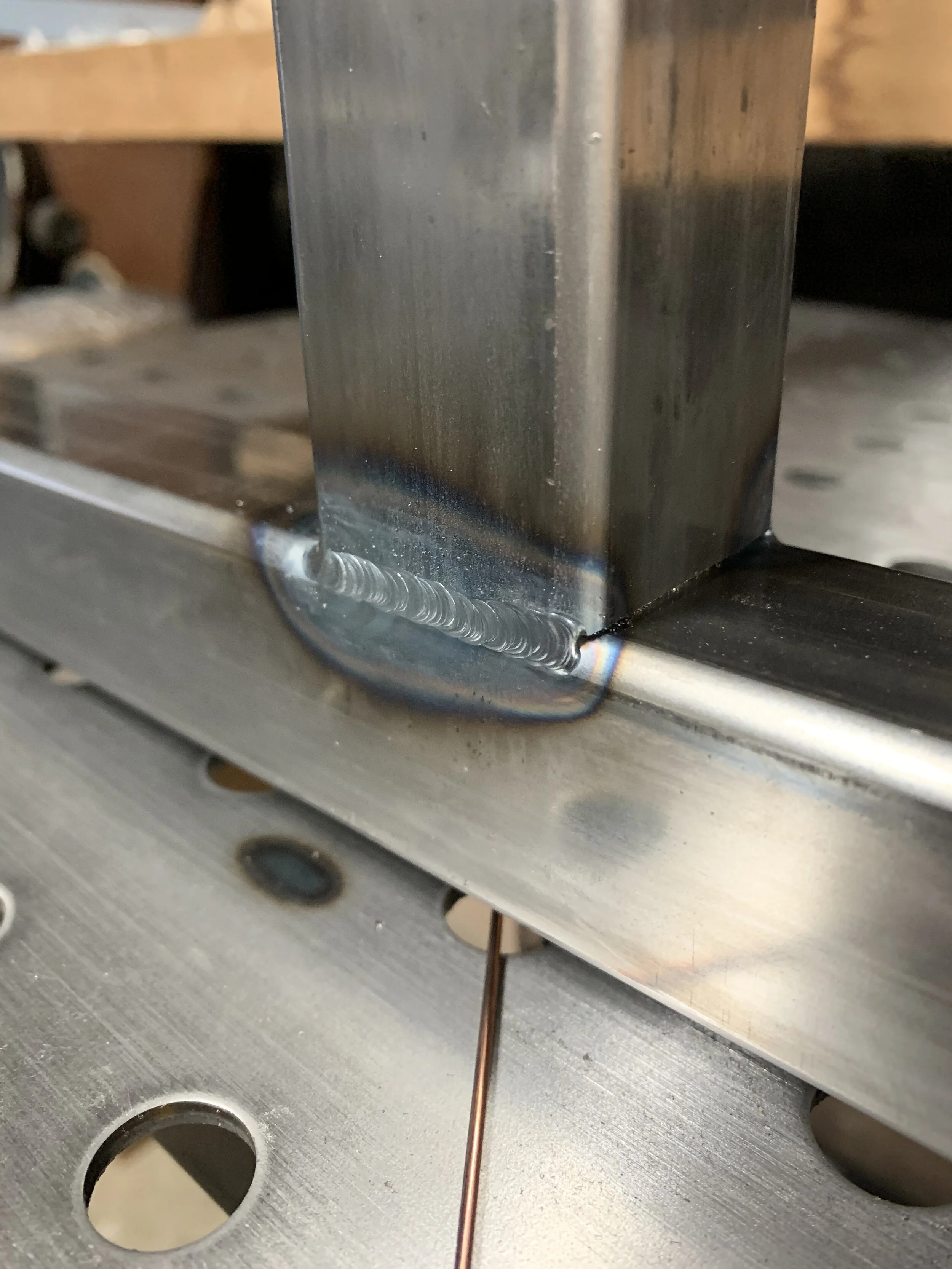


For the top plate I ordered 0.105” thick A569 Steel plate cut to size (30.0"X26.375") from OnlineMetals.com for ~$50.00. I don’t have equipment to cut plates like this, and it was the cheapest source I could find. When working with plate, heat tends to do weird things to it, so I actually tacked this to the milling machine braces in the middle of the stand first to keep that area flat as possible. After that I went along the edges in 3-4” increments moving to opposite sides of the plate for every bead. This actually resulted in a pretty flat surface in the end, but it did make me also which I had a water cooled torch. After I finished the welding, I ground around all the edges using a Porter Cable angle grinder with 120grit Flap Wheels. For the chip/coolant tray I took 1” x 0.125” bar and cut them at 12 degree opposing angles on each end. I then held them at this approximate angle on the side of the table and fusion tacked them into place. As each new piece came in I would bend them a little bit until they were all flush at the corners. This created a nice chip tray shape. I then proceeded to well along all these seams the same way I did with the top plate before - in 3-4” increments moving to the opposite sides after each bead. Once the stand framing was completely welded I made the side panel brackets out of the left over 1” X 0.125” bar stock I used for the chip tray. I cut these and 45 degree opposing angles, drilled them with a hole for a 1/4-20UNC tap and welded them inset 1/2” for the Birch Plywood I was planning on using. The final piece of the frame puzzle was drilling holes and welding in the 1/2-20UNC weld nuts to accommodate the leveling casters. I drilled these by hand with a drill and stepped bit. I used a magnet to fish out all the chips from this process before welding in the nut so that they weren’t rattling around the inside later. For the actual casters I ended up using 4 - Foot Master 550lb Capacity casters.
Painting and Finishing the Frame
With the welding out of the way, I used the angle grinder one more time to grind down the outer surface welds. I wanted a clean and seamless look to the frame once it was done. I gave the frame a quick wipe down with Mineral spirits to remove any of the oil left on the steel, laid down some cardboard and gave it to healthy coats of Rust-Oleum Paint & Primer Hammered Black Spray Paint. Overall, I’m pretty pleased with how it came out, the Rust-Oleum is pretty tough as long as you let it dry for a few days before putting it through its paces. For the side panels, I picked up 1/2” Birch plywood from the local Home Depot and stained it with Minwax Honey Stain. I marked the panel from the inside through the holes in the corner brackets I welded in the frame. I drilled these clearance holes by hand, and used 1/4” Stainless Finishing Washers with 1/4-20UNC Stainless Flat Head Cap Screws to attach them to the frame.


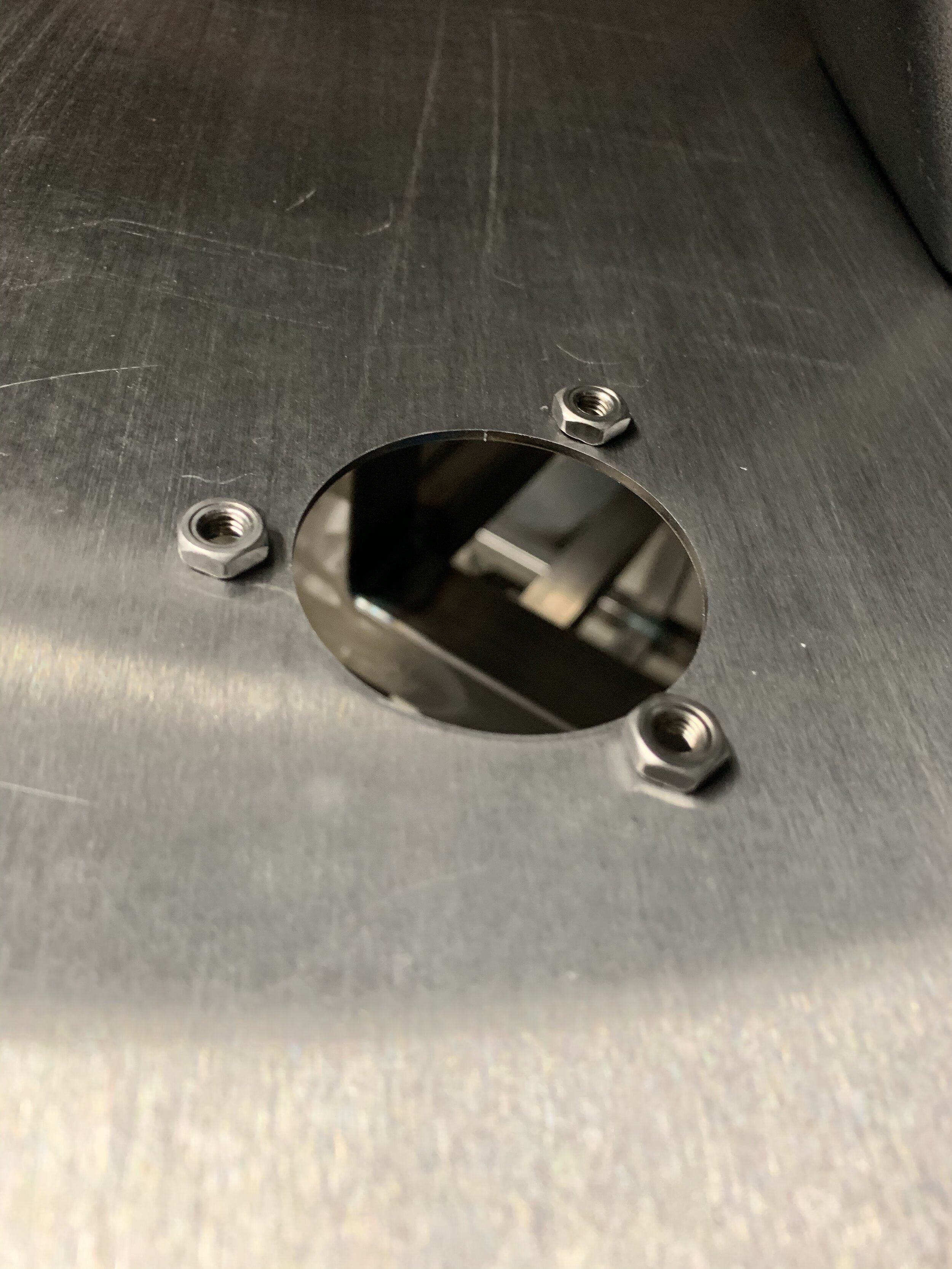
Since the cabinet slides in from the back of the stand I couldn’t use the same method for the inset panels because those brackets would prohibit installation and removal of the cabinet. I wanted to be able to take this out in the future so I ended up making another flat steel plate the covers the back to the edges, which I would attach by drilling and tapping holes directly into the frame. I actually decided to go a little crazy with this part because the way the mill sits in my garage the back of the machine is the first thing you see when you walk in from outside. I went to work in CAD and came up with what you see in the images below, I used a service called SendCutSend to have this plate made. You basically send them a .dxf or .ai file and 4 days later that shows up at your door step lasered (*pew* *pew*) from the material you chose on the website. It’s amazing times we live in. Aside from the branding, I wanted to hide all the cabling behind this plate so I also cut holes for power input, power output, and then a cable management system for everything that needs power on the mill. For the power inlet, I decided to use weld nuts to attach it so that I could remove it without taking the back plate off. I also painted this plate with the same hammered paint that I did for the frame.


Getting a little Extra & Bringing in THE Electronics
Originally I had planned on using the same stained side panels for behind the FARR cutout, but ultimately settled on something with a little more flair. If you haven’t seen my packaging and branding materials for the tooling, lately I have this fascination with Auroras. I wanted carry this design element over to this stand but rather than having it be static I wanted it to move and flow just like the Aurora does. I’ve done a few projects with Adafruit NeoPixels in the past and figured this would be a good starting point. If you don’t know what NeoPixels are you need to check them out. They are basically individually addressable RGB LEDs that you can program with a microcontroller. I ended up tracking the FARR cutout onto a piece of leftover plywood I had and started laying out the lights. I wanted them to follow the letters so the movement of the light would move with the letters in the end. I laid out the individual strips of NeoPixels (these come in a roll that you can slice down with a pair of scissors) to align with the tracing of the logo. I then proceeded to solder all the strips together in series using 24 gauge bridging wires like the diagram below. However, I used slightly different colors - red for the positive 5V terminal, white for the negative, and purple for the signal.


Ultimately, I ended up with 99 Lights, but an incandescent ain’t one. I wrote down the index of each light on the Frankenstein strip to help with the code & to keep track of the order and flow of the fades. Now part of making this thing look like its a swirling fade of color was finding a diffuser. After an extensive internet search I ended up settling on Arcylite 9K004 BC Color Changing Acrylic Sheet. I’d never actually used this before, but it seemed like it would fit the bill and they also cut it to size to the nearest inch. For my project I needed a 12” x 25” panel. Below is a video showing the test once I received the panel and had the program to a place where it reflected how I envisioned it.
Now that I had everything working and tested it was time to button it up and put it all together. I found that the best spacing for the panel away from the LEDs was about 2.375”. The provided vivid colors, but enough diffusion that your eyes could no longer see the LEDs as individuals anymore, now it was a pulsing and fluid singular display. I turned 4 stand-offs to this length on my lathe out of 1” round bar stock I had left over from another project. I also attached all the additional electronics (Arduino Uno & 5V 10Amp Power Supply) to the back of the lightbrite board, and then fastened everything together using a bit of double sided table along the top and bottom of the acrylic to keep things flat. Additionally, I wanted a way to turn on and off this feature so I ended up also wiring in a switch on the side of the stand. I found a really nice matte black toggle switched from a company called Buster & Punch that fit the aesthetic of the stand perfectly. I used a router to to recess it flush into the wood paneling and split the negative lead to the 5VDC power supply brick. For the rest of the cabling a used an IcoTek Pass-through. I use these all the time for equipment at my day job and they are great for passing plugs or large connectors through paneling. The 4 wires going into the start are the mill main power, the DRO, the x-powerfeed and the gooseneck light I installed on the side of the mill. All these terminate to a power strip that’s held to the back of the cabinet behind the panel using magnets.


With everything wired the stand was now finished. I’m not going to lie, it was actually kind of a bittersweet moment because this project has been with me so long. It was almost starting to seem like those project cars older guys get and work on continuously but never finish. While I had a plan for the original concept most of the other stuff kind of came into being organically as I continued to work on it, and in between I had loads of other things to occupy my time and my energy.

The finished stand with the back lit up like the 4th of JULYYY!
However, I did cross the finish line and I’m actually really happy with how it turned out. I probably could have saved a lot of time (and money) by simply buying the stock one from Precision Matthews, but thinking back saving time (or money) was never the objective. I wanted something completely custom that suited my needs for the space I’m in. In addition I wanted to try new ideas, practice my TIG skills, and maybe learn a few new things a long the way. With that in mind I guess I would say “mission accomplished.” I definitely won’t forget the first time it was buttoned up looking at the seamless single cable going into the back of the cabinet. I then flipped the switch on the side of the machine and FARR Frameworks lit up like the night sky above Norway in early March. It’s hard not to get a little bit excited in moments like these when it seems like you had a plan and vision all along and for a moment you can revel in this one success along a long line of other projects that didn’t seem to work out this same way. As I sat there taking it in (the patterns and movements of lights are actually quite mesmerizing) I heard a voice behind me say “Whoa, look at that.” Only then had I realized my garage was open and the increased foot traffic in the neighborhood from those restless from the CoVID shelter in place had gathered round to take a look. We awkwardly acknowledged each other as all humans seemingly do these days and carried on with our business knowing that to come to get a closer look would also mean having to be within 6 feet of another potentially asymptomatic person.
ToolS Recap
Materials Recap
2 - 20 foot lengths of 1.5” x 1.5” x 0.083” Square Steel Tubing
1 - 30” x 26.375” x 0.105” Cut to Size Plate
1 - 10 foot length of 1.00" x 0.125” Steel Bar Stock
1 - 4 foot length of 3.00” x 0.5” Steel Bar Stock
1 - 1lb Pack of 3/32” ER70-S2 Welding Rod
1 - 2’ x 4’ x 1/2” Birch Plywood Panel
4 - Cans of Rust-Oleum All-in-1 Paint & Primer - Hammer Black Color
1 - 4oz can of Minwax Oil-Based Stain - Honey Color
8 - 1/4” Stainless Steel Finishing Washers
8 - 1/4-20UNC x 0.5” Stainless Flat Head Cap Screws
4 - Foot Master 550lb Capacity Leveling Casters
1 - 12” x 25” Acrylite 9K004 BC Color Changing Acrylic Panel
1.5 Meters of Adafruit NeoPixel Strip LED lights
1 - 5V 10 Amp Power Supply
1 - 470 Ohm Resister
1 - 1000 mF 6.3V Capacitor
1 - Arduino Uno Microcontroller